1.0%u00A0%u00A0%u00A0%u00A0VESSELV-100%u00A0%u00A0%u00A0%u00A01%u00A0%u00A0%u00A0%u00A0
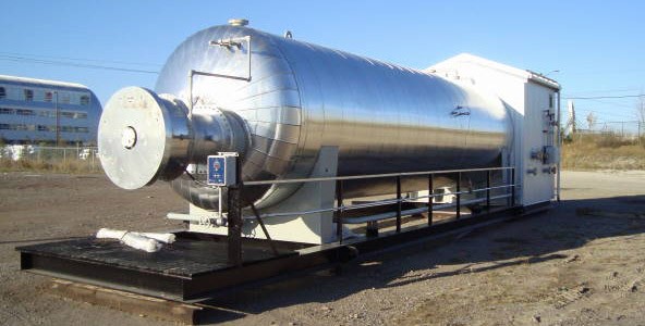
120" ID X 40'- 0" S/S x 75 psi MAWP HORIZONTAL TREATER%u00A0
Constructed with Alberta, BC and Saskatchewan registration
1/8" corrosion allowance on vessel, N/A on Firetube
250%u00B0F design temperature
Inlet deflector, Bolt in inlet slide
Two (2) Vortex breakers, weir with removable door and oil box
Radiography: RT-1
M.D.M.T.-20%uF0B0F @ 75 psig
Designed and Dressed 3 phaseVESSEL CONNECTIONS:N1%u00A0%u00A0%u00A0%u00A0Inlet%u00A0%u00A0%u00A0%u00A01%u00A0%u00A0%u00A0%u00A0-%u00A0%u00A0%u00A0%u00A0
8" NPS%u00A0%u00A0%u00A0%u00A0CL150 RF
N2%u00A0%u00A0%u00A0%u00A0Gas Outlet%u00A0%u00A0%u00A0%u00A01%u00A0%u00A0%u00A0%u00A0-%u00A0%u00A0%u00A0%u00A0
3" NPS%u00A0%u00A0%u00A0%u00A0CL150 RF
N3%u00A0%u00A0%u00A0%u00A0Oil Outlet%u00A0%u00A0%u00A0%u00A01%u00A0%u00A0%u00A0%u00A0-%u00A0%u00A0%u00A0%u00A0
6" NPS%u00A0%u00A0%u00A0%u00A0CL150 RF
N4%u00A0%u00A0%u00A0%u00A0Water Outlet%u00A0%u00A0%u00A0%u00A01%u00A0%u00A0%u00A0%u00A0-%u00A0%u00A0%u00A0%u00A0
4" NPS%u00A0%u00A0%u00A0%u00A0CL150 RF
N5%u00A0%u00A0%u00A0%u00A0Oil LC%u00A0%u00A0%u00A0%u00A01%u00A0%u00A0%u00A0%u00A0-%u00A0%u00A0%u00A0%u00A0
4" NPS%u00A0%u00A0%u00A0%u00A0CL150 RF
N6 a/b%u00A0%u00A0%u00A0%u00A0Water LC%u00A0%u00A0%u00A0%u00A01%u00A0%u00A0%u00A0%u00A0-%u00A0%u00A0%u00A0%u00A0
Two 4" NPS%u00A0%u00A0%u00A0%u00A0CL150 RF
N7%u00A0%u00A0%u00A0%u00A0PSV%u00A0%u00A0%u00A0%u00A01%u00A0%u00A0%u00A0%u00A0-%u00A0%u00A0%u00A0%u00A0
3" NPS%u00A0%u00A0%u00A0%u00A0CL150 RF
N8%u00A0%u00A0%u00A0%u00A0HLSD%u00A0%u00A0%u00A0%u00A01%u00A0%u00A0%u00A0%u00A0-%u00A0%u00A0%u00A0%u00A0
3" NPS%u00A0%u00A0%u00A0%u00A0CL150 RF
N9 a/b%u00A0%u00A0%u00A0%u00A0LG Condensate%u00A0%u00A0%u00A0%u00A02%u00A0%u00A0%u00A0%u00A0-%u00A0%u00A0%u00A0%u00A0
2" NPS%u00A0%u00A0%u00A0%u00A0CL150 RF
N10 a/b%u00A0%u00A0%u00A0%u00A0LG Water%u00A0%u00A0%u00A0%u00A02%u00A0%u00A0%u00A0%u00A0-%u00A0%u00A0%u00A0%u00A0
2" NPS%u00A0%u00A0%u00A0%u00A0CL150 RF
N11 %u00A0%u00A0%u00A0%u00A0PI%u00A0%u00A0%u00A0%u00A01%u00A0%u00A0%u00A0%u00A0-%u00A0%u00A0%u00A0%u00A0
2" NPS%u00A0%u00A0%u00A0%u00A0CL150 RF
N12%u00A0%u00A0%u00A0%u00A0TI %u00A0%u00A0%u00A0%u00A01%u00A0%u00A0%u00A0%u00A0-%u00A0%u00A0%u00A0%u00A0
2" NPS%u00A0%u00A0%u00A0%u00A0CL150 RF
N13%u00A0%u00A0%u00A0%u00A0Drain%u00A0%u00A0%u00A0%u00A01%u00A0%u00A0%u00A0%u00A0-%u00A0%u00A0%u00A0%u00A0
3" NPS%u00A0%u00A0%u00A0%u00A0CL150 RF
N14 a/b/c/d%u00A0%u00A0%u00A0%u00A0Anode %u00A0%u00A0%u00A0%u00A04%u00A0%u00A0%u00A0%u00A0-%u00A0%u00A0%u00A0%u00A0
4" NPS%u00A0%u00A0%u00A0%u00A0CL150 RF
N15 a/b/c/d%u00A0%u00A0%u00A0%u00A0FG Preheat 4%u00A0%u00A0%u00A0%u00A0-%u00A0%u00A0%u00A0%u00A0
2" NPS%u00A0%u00A0%u00A0%u00A0CL150 RF
N16%u00A0%u00A0%u00A0%u00A0TSHH%u00A0%u00A0%u00A0%u00A01%u00A0%u00A0%u00A0%u00A0-%u00A0%u00A0%u00A0%u00A0
4" NPS%u00A0%u00A0%u00A0%u00A0CL150 RF
N17%u00A0%u00A0%u00A0%u00A0FTLSD%u00A0%u00A0%u00A0%u00A01%u00A0%u00A0%u00A0%u00A0-%u00A0%u00A0%u00A0%u00A0
3" NPS%u00A0%u00A0%u00A0%u00A0CL150 RF
N18%u00A0%u00A0%u00A0%u00A0Oil LLSD%u00A0%u00A0%u00A0%u00A01%u00A0%u00A0%u00A0%u00A0-%u00A0%u00A0%u00A0%u00A0
3 NPS%u00A0%u00A0%u00A0%u00A0CL150 RF%u00A0%u00A0%u00A0%u00A0
N19%u00A0%u00A0%u00A0%u00A0Alt water out%u00A0%u00A0%u00A0%u00A01%u00A0%u00A0%u00A0%u00A0-%u00A0%u00A0%u00A0%u00A0
6" NPS%u00A0%u00A0%u00A0%u00A0CL150 RF
N20%u00A0%u00A0%u00A0%u00A0TC%u00A0%u00A0%u00A0%u00A01%u00A0%u00A0%u00A0%u00A0-%u00A0%u00A0%u00A0%u00A0
2" NPS%u00A0%u00A0%u00A0%u00A0CL150 RF
N21%u00A0%u00A0%u00A0%u00A0Oil TI/Spare%u00A0%u00A0%u00A0%u00A01%u00A0%u00A0%u00A0%u00A0-%u00A0%u00A0%u00A0%u00A0
3" NPS%u00A0%u00A0%u00A0%u00A0CL150 RF
N22%u00A0%u00A0%u00A0%u00A0FT Wash/ Spare%u00A0%u00A0%u00A0%u00A01%u00A0%u00A0%u00A0%u00A0-%u00A0%u00A0%u00A0%u00A0
3" NPS%u00A0%u00A0%u00A0%u00A0CL150 RF
M1%u00A0%u00A0%u00A0%u00A0Manway%u00A0%u00A0%u00A0%u00A01%u00A0%u00A0%u00A0%u00A0-%u00A0%u00A0%u00A0%u00A0
24" NPS%u00A0%u00A0%u00A0%u00A0CL150 RF c/w Blind and davit arm
FT1/2%u00A0%u00A0%u00A0%u00A0Firetube%u00A0%u00A0%u00A0%u00A02%u00A0%u00A0%u00A0%u00A0-%u00A0%u00A0%u00A0%u00A0
35x63" Nom%u00A0%u00A0%u00A0%u00A0Shop built%u00A0%u00A0%u00A0%u00A0%u00A0%u00A0%u00A0%u00A0%u00A0%u00A0%u00A0%u00A0%u00A0%u00A0%u00A0%u00A0Two (2) FIRE TUBES
24" OD x 42' Total Length "U" Firetube c/w stack
Sch XH (.500 thk) SA106 Gr. B
2.5 MMBTU/hr Each based on 10,000BTU/hr/ft2
1/16" corrosion allowance
Five-piece mitre2.0%u00A0%u00A0%u00A0%u00A0INSTRUMENTATION
LC-100/101%u00A0
2 FISHER L2 LEVEL CONTROLLERS
2" NPT Connection
Snap Acting 0%u201035 Psi Output
1 7/8" x 12" PVC Displacer
Complies to NACE MR0175%u20102002LIT-100%u00A0
1 VEGAFLEX 81 GUIDED WAVE RADAR LEVEL TRANSMITTER
P/N FX81.FE3AGGHXDNXX
TDR sensor for Continuous Level & Interface Measurement of Liquids
E = Approval: Fm (Xp) Cl I, Div1, Gp Abcd
A = Version/Material:Exchangeable Coated Cable
(dia.: 4mm) With Uncoated Centering Weight / Pfa And 316
Ag = Process Fitting/Material: Flange 4" 150lb Rf, Asme B16.5 / 316/316l
G = Seal / Second Line Of Defense / Process Temperature:
Fkm (Shs Fpm 70c3 Glt) / With / -40 To +150c
H = Electronics: Two-Wire 4-20ma / Hart
X = Supplementary Electronics: Without
D = Housing / Protection: Aluminium Double Chamber / Ip66/Ip68 (0.2bar)
N = Cable Entry / Connection: 1/2" Npt / Blind Plug
X = Display / Adjustment Module Plicscom: Without
X = Certificates:LCV-100%u00A0
1 KIMRAY 612 FMT DB PO LIQUID CONTROL VALVE
11-13 weeks Part # EXXS6V
6" CL150 RF Process Connections
Pneumatic Actuator, Fail Closed
Sour ServiceLCV-101%u00A0
1 KIMRAY 325 FMT PB PO LIQUID CONTROL VALVE
11-13 weeks Part #MYH5S6V
3" CL150 RF Process Connections
Pneumatic Actuator, Fail Closed
Sour ServiceLG-100%u00A0
1 QUALITY OR EQUAL LIQUID LEVEL GAUGE
V.L. 52"
Model: Q48T20, Transparent
4 Section, CS, Nace
Max Pressure: 1250 PSI @ 100 F
C/w Quality Gaugecock Valves
1 Set, Offset, Model: Q146
3/4" MNPT Vessel x 1/2" FNPT Gauge x 1/2" FNPT Vent / Drain
Max Pressure: 2500 PSI @ 100 F, NaceLG-101%u00A0
1 QUALITY OR EQUAL LIQUID LEVEL GAUGE
V.L. 40-7/8"
Model: Q39T20, Transparent
3 Section, CS, Nace
Max Pressure: 1250 PSI @ 100 F
C/w Quality Gaugecock Valves
1 Set, Offset, Model: Q146
3/4" MNPT Vessel x 1/2" FNPT Gauge x 1/2" FNPT Vent / Drain
Max Pressure: 2500 PSI @ 100 F, NaceLSLL-100/101%u00A0
5 VEGASWING 63 ELECTRIC LEVEL SWITCHESLSHH-100/101/102%u00A0
3/4" NPT Process Connections
2 Pole, 6" Probe w/ High Temp OptionPIT-100%u00A0
1 ROSEMOUNT 2088 PRESSURE TRANSMITTER
Model# 2088G2S22A1M5B4C6
G: Transmitter Type: Gage
2: Pressure Range: -14.7-150 Psi
S: Output: 4-20 mA DC/Digital HART Protocol
22: Material of Construction: 316L SST / Silicone Fill
A: Process Connection: 1/2" NPT Female
1: Conduit Thread: 1/2" NPT
M5: LCD Display, Scaled 0-100%
B4: SST Mounting Bracket with SST Bolts
C6: CSA Explosion-Proof; Intrinsically Safe, and Non-Incendive
PI-100 1 WGI OR EQUAL PRESSURE GAUGE
Silicone Filled
4" dia. Face x 1/2" NPT Bottom Mount End Connection
SS Case and Internals
0 to 100 Psi, Dual Scale
TI/TW-100%u00A0
1 MASTER-TEMP 300 OR EQUAL TEMPERATURE GAUGE
1/2" NPT Back Connection
3" Dial, 9" Stem
-40 to 160 F Range - Dual Scale
C/w 1/2" FNPT x 3/4" MNPT x 9.25" OAL, 7.5" U, 316 SST ThermowellANO-100-103%u00A0
4 ANODES
3" x 22" 17# Aluminum Anode
4" CL150 RF Connection
C/w Pigtail Wire Without Shunt3.0 FUEL GAS
V-200%u00A0
1 8" OD X 30" OAL 150 PSI SWEET MAWP FUEL GAS SCRUBBER
Mechanical HLSD (Reduces Outlet to 1" NPT)
1/16" Corrosion Allowance
-20/650 F Design Temperature
Registered in Alberta, BC, Sask. & ManitobaPSV-202%u00A0
1 MERCER PRESSURE RELIEF VALVE
Model 9100
1" NPT Inlet x 1" NPT Outlet
Sweet Service Trim, WCB Body"D" Orifice, 150 Psig Set PressurePI-200%u00A0
1 WGI OR EQUAL PRESSURE GAUGE
Silicone Filled
2.5" dia. Face x 1/4" NPT Bottom Mount End Connection
SS Case and Internals
0 to 200 Psi, Dual ScalePRV-300/%u00A0
3 CVS OR EQUAL 67CFR INSTRUMENT REGULATOR
301/302 1/4" FNPT Connections
Sweet Service Trim
250 Psi MAWP
0 to 35 Psi Spring Range, Tapped Bonnet4.0 BURNER MANAGEMENT SYSTEM%u00A0
NOTE: CSA B149.3 COMPLIANT CONTROLSBMS-200%u00A0
1 PROFIRE 2200 BMS Controller
Combustion Safety Controller
Pre Wired
This controller can control both burners.FABS-100%u00A0
2 FLAME ARRESTED BURNER SYSTEMS
Rated for 2.25 MM BTU/hr to fit 24" firetube
C/w Burners & Air Plate
C/w Secondary Control Plate c/w 5" Burner pilot adjustable shutterTCV-200%u00A0
2 KIMRAY 1400 SMT MOTOR VALVES
1" NPT, 1/2" Orifice 10 Psi SpringLSLL-200%u00A0
1 VEGASWING 63 ELECTRIC LEVEL SWITCH
3/4" NPT connection, 2 Pole, c/w High Temp Option, 12" ProbeSOV-200-3%u00A0
4 ASCO SOLENOID VALVES
Four (4) 24 volt, 1" NPT connections
SOV-200-3 4 ASCO SOLENOID VALVES
Two (2) 24 volt, 1/4" NPT connections, 3 Way
Two (2) 24 volt, 1/4" NPT connections, 2 Way
SPV-200/201 2 SPEED RESTRICTOR VALVES
1/4" NPTPSHH/PSLL-200%u00A0
4 UE HIGH / LOW PRESSURE SWITCHES
For Profire Burner System
(3 to 50 psi)TSHH/TSH-200%u00A0
2 ELECTRIC TEMPERATURE SENSORS
Wika TC-10 Dual Process Head Type K Thermocouple
3/8" Bore X 11.5"
C/w 3/4" NPT X 11.5" Stem, stainless steel thermowellPI-201-205%u00A0
10 PRESSURE GAUGES
Liquid fill
2-1/2" dia. face x 1/4" NPT end connection
Four (4) 0 to 15 psig range, dual Scale
Six (6) 0 to 30 psig range, dual ScalePRV-200/202 2 FISHER MODEL 627R PRESSURE REDUCING REGULATORS
1" NPT end connections
Steel Body construction
5 to 20 psig spring range
1/2" orificePRV-201/203%u00A0
2 FISHER 67CFR REGULATORS
1/4" FNPT connections
STD service trim
250 psig MAWP, 0 to 35 psig spring rangePSV-200/01%u00A0
2 MERCER PRESSURE RELIEF VALVES
Model 9100
1" NPT inlet x 1" NPT outlet
Sweet service trim, WCB body"D" Orifice, 30 psig set pressure
2 1" CL3000 NPT Alta Y-Strainer LF2
4 1" NPT CL3000 Ball Valves
6 1/2" NPT CL3000 Ball Valves
4 1/4" NPT CL3000 Ball Valves
5.0 MANUAL VALVES1%u00A0
8" CL150 RF RP, Meridian or Equal Ball Valve, Nace Service
2%u00A0
6" CL150 RF RP, Meridian or Equal Ball Valve, Nace Service
1%u00A0
3" CL150 RF FP, Meridian or Equal Ball Valve, Nace Service
6%u00A0
3" CL150 RF RP,Meridian or Equal Ball Valve, Nace Service
5
1" CL2000 NPT RP, Meridian or Equal Ball Valve, Sweet Service
3%u00A0
1" CL2000 NPT FP, Meridian or Equal Ball Valve, Sweet Service
1%u00A0
3/4" CL2000 NPT RP, Meridian or Equal Ball Valve, Sweet Service
7%u00A0
1/2" CL2000 NPT RP, Meridian or Equal Ball Valve, Nace Service
1%u00A0
1/2" CL2000 NPT RP, Meridian or Equal Ball Valve, Sweet Service
5%u00A0
1/4" CL2000 NPT RP, Meridian or Equal Ball Valve, Sweet Service
1%u00A0
6" CL150 RF RP, C&C or Equal Swing Check Valve, Nace Service
1%u00A0
3" CL150 RF RP, C&C or Equal Swing Check Valve, Nace Service
1%u00A0
1/2" CL2160 NPT, OMB or Equal Swing Check Valve, Std Service
2%u00A0
1/2" CL2160 NPT, OMB or Equal Swing Check Valve, Nace Service
1%u00A0
1/2" CL6000 NPT Gaugetech or Equal Needle Valves, SS
11%u00A0
1/4" CL6000 NPT Gaugetech or Equal Needle Valves, CS
1%u00A0
6" CL150 RF Bleed Ring 316SS c/w 1/2" NPT Port, 1-1/2" thk
1%u00A0
3" CL150 RF Bleed Ring 316SS c/w 1/2" NPT Port, 1-1/2" thk
6.0 SKID AND BUILDING SPECIFICATION
SK-100%u00A0
1 SKID BASE, 11'- 0" W X 48'- 6" L
Main Skid & Vessel Support Members - W12 @ 45#
Intermediate Support Members - C8 @ 11.5#
Four (4) Lifting Lugs7.0 ELECTRICAL
Electrical connection of burner management system is included.%u00A0
Any additional electrical scope is supplied and installed by others.8.0 PACKAGING SPECIFICATIONS
Instrumentation
- All Instrument Air devices vented at device.
- All Other devices to be vented off skid individually.
Vessel Inlet
- Vessel inlet is 8" CL150 welded and flanged, field installed.
Gas Outlet
- Gas outlet is 3" CL150 welded and flanged, it passes through a spool for future meter run before being directed to skid edge.
Condensate Outlet
- Condensate outlet is 6" CL150 welded and flanged, it passes through the LCV before being directed to skid edge.
Water Outlet
- Water outlet is 4" CL150 welded and flanged, reduces to 3" before passing through the LCV and being directed to skid edge.
Drain
- Drains are 3" CL150 welded and flanged, equipped with ball valve and blind.
Relief Valve
- PSV outlet is 4" CL150 welded and flanged, reduced to 3" and equipped with ball valve.
Instrument Air / Fuel Gas System
- Fuel gas and instrument air headers are 1" NPT provided from off skid @ 150 Psi.Shipment
- All flanged and open ends of piping will be covered for shipment.
- Package is readied or dismantled only to the extent required for shipping.
- All piping, instrument tubing and equipment will be adequately supported.
- Piping to skid edge c/w individual connections.Additional Specifications
- Vessel and piping are fully flanged.
- Free Issued Items to be delivered to CAPE Prepaid and Ready to be Installed.
9.0 MATERIAL SPECIFICATIONS
a) Pressure Vessels
Heads SA-516-70N
Shell SA-516-70N
Internals SA-36
Saddles / Base Plate SA-36
Pipe SA-106-Gr.B SMLS
Flanges SA-350LF2
Weld Fittings SA-234-WPBb) Threaded Piping
Pipe SA-106-B
Threaded Fittings SA-105N, CL3000c) Welded Piping
Pipe SA-106-B, 2" Sch. 80 SMLS, 3" & 4" Sch. 40 SMLS
Flanges SA-105-N
Weld Fittings SA-234-WPB
Threadolets and Couplings SA-105-N
Gaskets 1/8", 316SS, Graphoil Filled
Bolting SA-193-B7M, SA-194-2HMd) Instrument Tubing
Tubing 316 SS 3/8" .035 wt and 1/2" 0.049 on Process
Fittings SS, Hy-Lok
Ferrules SS, Hy-Lok
* Piping to be built as ASME B31.3 Category Normal
* Piping AB83 forms included for Owner registration of piping with ABSA. It is the owner's responsibility to provide an inspector for pressure piping and sign off on AB-83 form. This must be completed by the owner before any piping system is put into service.
10.0 TESTING / PWHT SPECIFICATIONS
a) Hydrotesting
Pressure Vessels Will be Hydrotested to at least 1.3 Times Maximum Allowable
Working Pressure as per ASME Section VIII
Pressure Piping Will be Hydrotested to 1.5 Times Maximum Allowable Working
Pressure as per B31.3b) Radiography
Vessels RT-1 By others
Piping 100% X-Rayc) PWHT
Vessels Firetube Only By others
Piping Nod) Other NDE
Ultrasonic Testing No
Hardness Testing No
Magnetic Particle Testing 100% on Firetube Fillet Welds Only By others
Production Impact Testing No11.0 PAINT AND COATING SPECIFICATIONS
a) External Paint Specifications
Vessel External Surface Preparation%u00A0
SSPC-SP#6
Skid & Piping External Surface Preparation%u00A0
SSPC-SP#3
External Primer%u00A0
One (1) Shop Coat of Cloverdale PrimerVessel External Finish Paint%u00A0
One (1) Shop Coat of Cloverdale Desert Tan Enamel
Stack External Finish Paint%u00A0
One (1) Shop Coat of High Heat Black Enamel
Skid & Piping External Finish Paint%u00A0
One (1) Shop Coat of Cloverdale Desert Tan Enamelb) Internal Coating Specifications
Internal Surface Preparation%u00A0
None Included
Internal Coating%u00A0
None Included
Firetube Coating%u00A0
None Includedc) Insulation and Cladding Specifications
Vessel & Piping External Insulation None Included
Delivery:
Stock 10' x 40': Mostly built. please allow 4-6 weeks for completion
Show Less