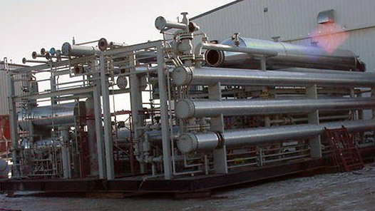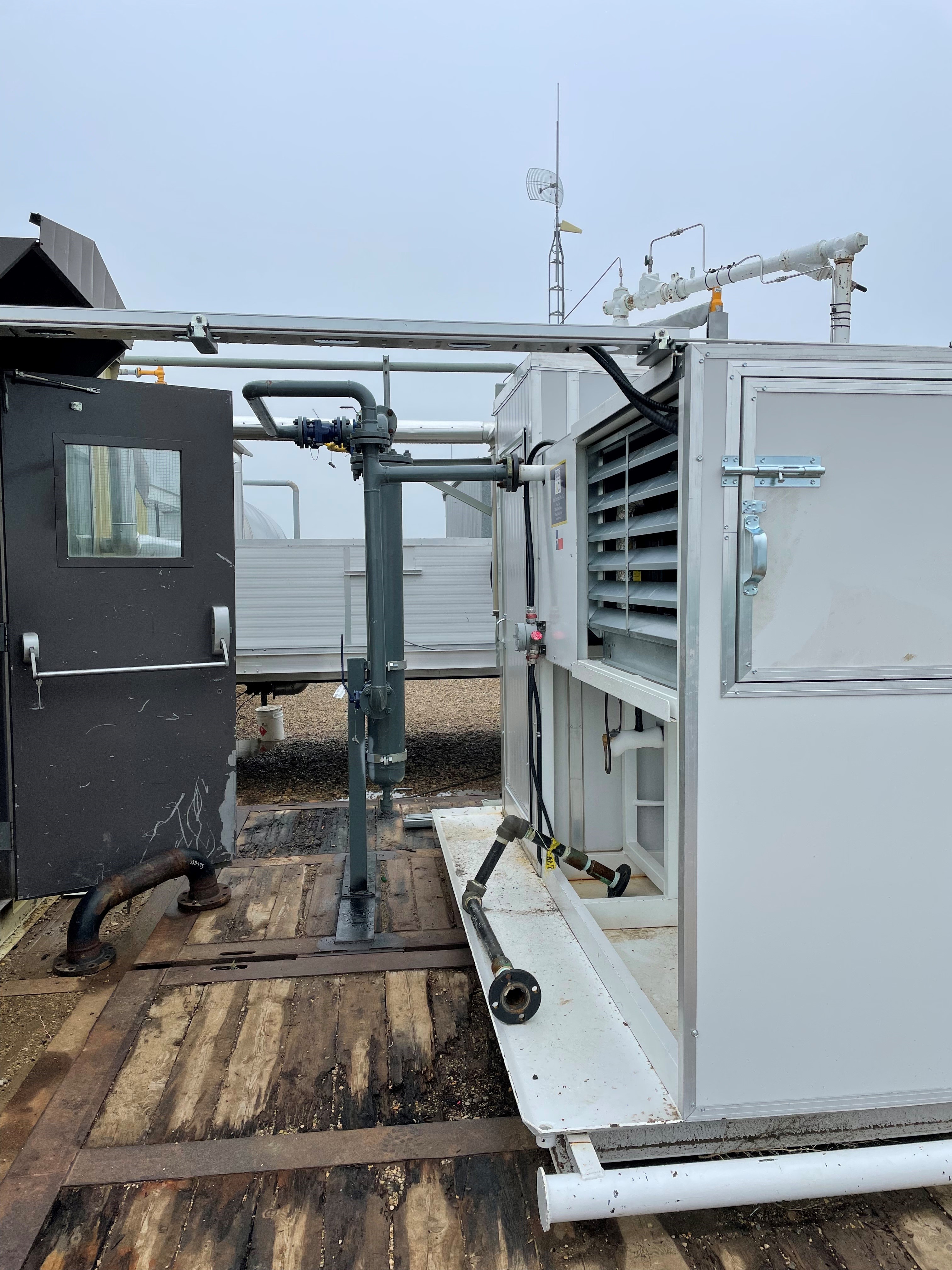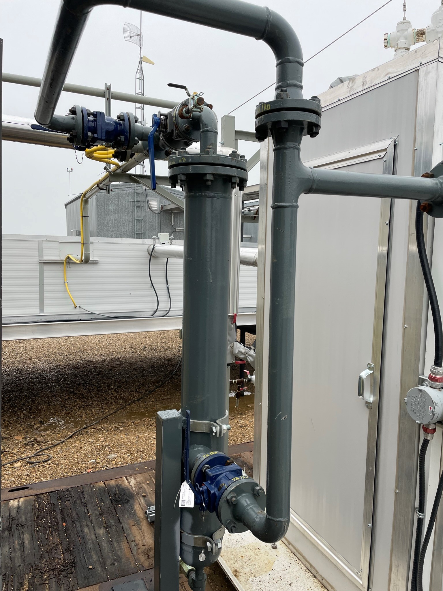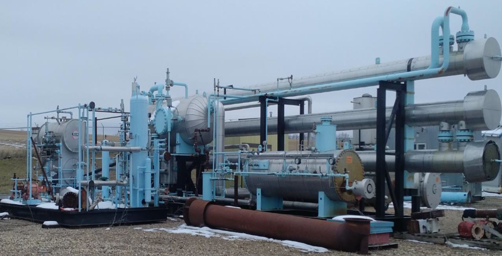
This unit is built in such a way that it can be scaled up to 30 and 40 MMSCF/d capacity without requiring major refitting.
Unit is skidded and housed.
Project cancellation caused unit to be surplus.
Molecular Sieve Package (20 MMSCFD )
1. DESIGN CONDITIONS:
Design• Gas Flow Rate (std m3/d) 564,000 Initial (~20.0 MMscfd)• Operating Pressure (kPag) 11000 Normal• Inlet Temperature (%u00B0C) 70 Max• Gas Molecular Weight See Gas Composition• Design Pressure (kPag) of Major Equipment 14,200• Design Temperature (%u00B0C) of Major Equipment Refer to Individual Data Sheets• Fuel Gas Sweet (by customer)• Electrical Classification Class 1, Zone 2• As per UOP Recommendations,• Regeneration system is designed for flow rates of 170 std e3m3/d (6.0 MMSCFD).
PROCESS COMMENTS
Inlet Gas Cooler E100 • 7.2 x 12 x 4RF 10130.3 FT%u00B2 ext surface.
Horizontal Sep. V200 • 914.4 mm OD x 3048 mm S/S Horizontal• D.P./D.T.: 14,200 kPa @ 50%u00B0C MDMT -29%u00B0C
Inlet Filter Coalescer V210 • 406.4 mm ID x 2,590 mm S/S Vertical• D.P./D.T.: 14,200 kPa @ 50%u00B0C MDMT -29%u00B0C
Molecular Sieve Towers C-400/410 • 1372 mm ID x 7010 mm S/S Vertical• D.P./D.T.: 14,200 kPa @ 316%u00B0C MDMT -46%u00B0C
Regeneration Gas Heater H480 • Salt Bath 1828 mm OD x 6096 mm S/S• Net Duty 5.75 MMBtu/hr
Regeneration Gas Cooler E450 • 7.2 x 12.0 x 4RF
Regeneration Gas Separator V430 • 323.9 mm OD x 1524 mm S/S Vertical• D.P./D.T.: 14,200 kPa @ 180%u00B0C MDMT -29%u00B0C
Outlet Dust Filter • 406.4 mm OD x 1,397 mm S/S Vertical• D.P./D.T.: 14,200 kPa @ 50%u00B0C MDMT -29%u00B0C
From the original quote:
This molecular sieve dehydration unit with bottom up heating is designed to meet your outlet specifications. It is important to note that the Molecular sieve has been chosen over the Silica Gel for this application for two reasons:
1) The silica gel material will remove moisture as requested in the RFQ. The a silica gel system would have two towers diameter ~ 6ft vs 4.5 ft. If the intent of the silica gel is to eventually remove hydrocarbons for hydrocarbon dew point control. It is important to note that the silica gel selected will remove moisture only. The silica gel which is utilized for hydrocarbon and dew point control will foul in the presents of high concentrations of H2S and heavy hydrocarbons.
2) The molecular sieve material offers water dew point control with a smaller diameter tower then the silica gel. Natco selected molecular sieve, if the client requires a silica gel quotation the tower diameter and the regeneration flow will increase. A further decrease in cost can be realized if the client could increase the outlet specification from a water dew point less than -10 %u00B0C at 5516 kPa. This option should be seriously considers prior to order.
Natco has increased the flange rating around the regeneration system to compensate for the high regeneration temperatures. It is important to note that the design pressure was calculated by the following industrial standard method:• Max Operating Pressure + 15% = Design Pressure• 12,400 kPa x 1.15 ~ 14,200 kPa Thus, a design pressure of 14,200 kPa has been used. • This design pressure will allow operating room prior to a conventional PSV lifting (typical to leave 10%). • The design pressure of 316%u00B0C caused an increase in flange rating.• Flange Rating 900 # 1500#• 82%u00B0C (180%u00B0F) 14,200 kPa• 260%u00B0C (500%u00B0F) 12,367 kPa 20,635 kPa• 316%u00B0C (600%u00B0F) 11,300 kPa 18,844 kPa
Natco has gone to a 1500# orbit valve in-order to find a carbon steel mating flange. The Orbit valves are categorized under ANSI B16.34 can uses a 900# flange @ 600%u00B0F and meet a 12,500 kPag design pressure. Natco would like to substitute to valve specifically design to handle the material the softer molecular sieve material rather then the more abrasive silica gel material at a price savings.
Orbit Valves estimates a saving of 30 to 50% in the valve pricing.
Natco experience with high H2S regeneration is system is that they are prone to sulfur fouling of the air cooler. It is a standard procedure to heat the gas to the air cooler and melt the sulfur the regenerator separator. This procedure is conducted during the stand-by time on the regeneration cycle. Natco has maintain the 1500# flange rating to the regeneration separator which will allow this procedure. Natco also recommends a slight continuous flow through the heat in-order to prevent hydrate formation.
Natco Canada, Ltd. has not coated the process water piping or vessels in this quotation, however believe that this should be considered.
Natco has design the unit using the information provided below:
Gas Composition (dry)• H2 0.01• He 0.02• N2 0.90• CO2 5.11• H2S 11.32• C1 82.54• C2 0.09• C3 0.01• C4+ 0.00
Product Specification• Water dewpoint less than -10 %u00B0C at 5516 kPag• Hydrocarbon dewpoint less than -10 %u00B0C at 5516 kPag• Normal outlet pressure 11,000 kPag• Minimum outlet pressure 8,300 kPag• Maximum outlet pressure 12,400 kPag• Max outlet temp 49 %u00B0C
The composition provided does not require any hydrocarbon dew point control.
The Mechanical design has been done according to the RFQ. As listed below.
1. Inlet air cooler* (loose)
2. Inlet separator c/w gas & liquid meters (2 phase with connections for 3 phase) +
3. Inlet coalescing filter separator*
4. Adsorption towers*
5. Outlet dust filter+
6. Regeneration gas air cooler * (loose)
7. Regeneration gas separator+
8. Regeneration gas heater+ (loose)
9. Sour water flash drum (receives high pressure water from inlet separator, regeneration gas separator, & inlet filter separator) including gas & liquid metering+ (Not included at this time.)
10. Fuel gas system including PCV, scrubber c/w auto dump, meter (P&T compensated), ESDV and PSV and have capacity for future site expansion and compression+ (Not enough information to design for compression)
11. All switching and control valves+
12. All controllers & transmitters+
13. Auto blow down valves for main gas, regeneration gas, and fuel gas+
14. Program for time cycle control*
15. Interconnecting piping+
16. Structural skids+
17. Buildings+ * Size for 564 e3m3/d + Size for 1127 e3m3/d
2. SALT BATH HEATER:• -One (1) 72" OD x 20'-0" S/S• -(2) Non-Removable 20" OD x 20'-0" long (one way) firetube 5.75 MMBTU/hr total net duty• -Internals seal welded one side only where required for process, stitch welded otherwise• -Coil, See Below.• -Note: Fire tube liner is not included in quotation.
NOZZLES:• N1 Regeneration Gas Outlet 3" 1500# RTJ• N2 Regeneration Gas Inlet 3" 1500# RTJ• N3 Drain 2" 150# RF• C1 TI 1" 3000# NPT• C2 TSH 1" 3000# NPT• C3 TC 1" 3000# NPT• F1 Fill hatch 18" obround opening
MATERIALS/SPECIFICATIONS• Shell: SA-516-70 / SA36• Heads: SA-516-70 / SA36• Skirt/Saddle: SA-516-70 / SA-36• Externals: SA-516-70 / SA-36• Internals SA-516-70-1/4"• Flanges: SA-105N• Couplings/T.O.L's SA-105N• Gaskets: 316 SS• Bolting: SA-193-B7M, SA-194-2HM• C.A.: 1/8"• Registration: None• Radiography: None• PWHT: None• Hydrotesting: Fill and leak test• UT: none• MPI: none• Hardness: none• Select Chemistry: none
3. SALT BATH HEATER COIL:• -Twenty (20) Passes of 3" pipe x 14,200 kPa @ 315/-29%u00B0C• -20'-0" long• -Short radius return bends• -Non-Removable• 900# ANSI:• Pipe: SA-106B (2" SCH 160)• Fittings: SA-234-WPB• Flanges: SA-105N RF• TOL'S: SA-105N (3000#)• Gaskets: 316 SS Flexitallic• Bolting: SA-193-B7M, SA-194-2HM• C.A.: 3.2 mm ( internal only )• Radiography: 100% (Severe)• PWHT: Yes• Hydrotesting: 1.5 times design pressure• UT: none• MPI: Yes, All welded joints• Hardness: Yes, Max 200 HB Brinell• Select Chemistry NACE MR-75-01
4. BUILDING HEATERS:• -Two (2) 25 kW Ruffneck building heaters, Model # FX420-480360-25.• -Heater sizing may changed based on detailed design.•
5. INLET COOLER• Data sheet available on request
6. HYDRO TESTING• -Vessels - 1.3x Design• -Piping - 1.5x Design or maximum flange rating• -Tubing - tested at operating pressure• -Vessels - 1.3x Design• -Piping - 1.5x Design or maximum flange rating• -Tubing - tested at operating pressure
7. INSTRUMENTATION:• See attached instrument list for instruments and manual valves.
INSTRUMENT TUBING:• Instrument supply/drains• Size (W.T.): 3/8" (0.035")• Fitting brand name: Swagelok• Fitting material: 316SS• Ferrules material: 316SS• Tubing material: 316SS• Tubing clips: SS and/or Plastic• Pressure test: Air tested to normal operating pressure• Process leads• Size (W.T.): 1/2" (0.065" for 900# section)• Fitting brand name: Swagelok• Fitting material: 316SS• Ferrules material: 316SS• Tubing material: 316SS• Tubing clips: SS and/or Plastic• Pressure test: Air tested to normal operating pressure-Quantities and sizes as• listed on the attached P&ID's.• NOTE: Unit to be disassembled only to the extent required for shipping.
8. PIPING SPECIFICATIONS:
PIPING:
150# ANSI• Pipe: SA-106B (As per Specification)• Fittings: SA-234-WPB• Flanges: SA-105N RF• TOL'S: SA-105N (3000#)• Gaskets: 316 SS Flexitallic• Bolting: SA-193-B7M, SA-194-2HM• C.A.: 3.2 mm• Radiography: 10% (Normal)• PWHT: none• Hydrotesting: 1.5 times design pressure• UT: none• MPI: none• Hardness: none• Select Chemistry none• Select Chemistry NACE MR-0175
900# ANSI• Pipe: SA-106B (Thickness as per Specification)• Fittings: SA-234-WPB• Flanges: SA-105N RF• TOL'S: SA-105N (3000#)• Gaskets: 316 SS Flexitallic• Bolting: SA-193-B7M, SA-194-2HM• C.A.: 3.2 mm• QUOTATION• Box 850, Station "T", Calgary, Alberta T2H 2H3• Tel: (403) 236-1850 Fax: (403) 236-0488• D:\ENG\Estimate\Priced Quotes\Q-1U974375.doc Page 9• Radiography: 100%• PWHT: Yes 19mm• Hydrotesting: 1.5 times design pressure• UT: none• MPI: Yes, all fillet welds.• Hardness: Yes, Max 200 HB Brinell• Select Chemistry NACE MR-0175
900# ANSI outside building• Pipe: SA-333-GR.6 (Thickness as per Specification)• Fittings: SA-420-WPL6• Flanges: SA-350-LF2 RF• TOL'S: SA-350-LF2 (6000#)• Gaskets: 316 SS Flexitallic• Bolting: SA-193-B7M, SA-194-2HM• C.A.: 3.2 mm• Radiography: 100%• PWHT: Yes, 19.0 mm• Hydrotesting: 1.5 times design pressure• UT: None• MPI: Yes, all fillet welds.• Hardness: Yes, Max 200 HB Brinell• Select Chemistry NACE MR0175
9. BUILDING:• -Self-framing gable roof metal building, 14'-0" x 50'-0" x 12'-0" low eave (approximately).• -Exterior 22 gauge (0.0336") pre-painted steel (colour TBA)• -Interior 24 gauge fluted aluminium sheet liner, colour: white• -R12 wall & R20 roof insulation, both with 4 mil vapour barrier• -Two (2) 40" x 40" double glazed sliding windows c/w screen• -One (1) single door c/w panic hardware, canopy, IWG 24" and 24" check chain, weather-strip,• sweep, threshold, lockset• -One (1) double door c/w panic hardware, canopy, IWG 24" and 24" check chain, weather-strip,• sweep, threshold, lockset• -Four (4) 30" x 18" adjustable louvers c/w screen• -Continuous ridge vent• -Four (4) building exhaust fans (two (2) high, two (2) low)• -Ice rake, 100'-0"
10. STRUCTURAL STEEL SKID:• -One (1) 14'-0" x 50'-0" structural steel skid• -3" x 3" x 3/16" angle floor support• -1/4" flat plate floor (seal welded interior, stitch welded perimeter)• -Two (2) floor drain sumps per skid, with 2" piped to nearest skid edge (Natco standard)• -3" high skid perimeter drip lip (seal welded on inside only)• -Six (6) point jack and roll lift• -3 Ton trolley for servicing 6" Orbit valves.• -3" Fire retardant insulation under building• -Note: Structural steel is not designed for low temperature• -Skid drains are not insulated or heat traced• Note: The towers, regeneration gas heater, and regeneration gas cooler are stand-alone and• mounted on foundation by others.
11. PAINTING AND SURFACE PREPARATION:
SANDBLAST
System #1• -Sandblast to SSPC-SP6• -Prime: (1) coat (1.5-2.0 mils DFT) of Cloverdale T-810 primer• -Finish: (2) coats (2.5-3.0 mils DFT) of Cloverdale 74/76 series enamel (Colour: F-34 Warm Grey)• -Design temperature up to 93C
System #2• -Sandblast to SSPC-SP10• -Prime: none• -Finish: (2) coats (1-1.5 mils DFT per coat) of Cloverdale 83207 Heat Resistant Silicone Acrylic• (Colour: Grey)• -Design temperature up to 205C
System #3• -Applies to uninsulated areas only, (flange projections, flanges etc.)• -Sandblast to SSPC-SP10• -Prime: (1) coat (2-3 mils DFT) Clovazinc II• -Finish: (2) coats (1 ½-2 mils DFT per coat) of Cloverdale 70020 hi-heat silicone, black• -Design temperature up to 316C
System #4 (structural steel)• -Sandblast to SSPC-SP6• -Prime: (1) coat (1.5-2.0 mils DFT) of Cloverdale T-810 primer• -Finish: Top of floor: (2) coats (2.5-3.0 mils DFT) of Cloverdale 74 series (Colour: black) c/w non-skid• grit additive• Elsewhere: (2) coats (2.5-3.0 mils DFT) of Cloverdale 74/76 series (Colour: Black)
12. INSULATION:
Vessels ( Mole Sieve Towers C401/402, Regeneration Gas Heater H401)• - Insulation type: Calcium Silicate• - Insulation thickness 3" (75mm)• - Banded with 19mm wide SS strapping on 305-mm centres• - Cladding is smooth aluminium• - The heads will be covered with smooth aluminium• - Manway covers/blankets not included.• - Valve blankets for high temperature valves
Process Piping• - Insulation Type: Calcium Silicate• - Insulation thickness: As specified on the P&IDs
13. ELECTRICAL:
(OPTIONAL see options)
Electrical• 1. Supply, install and/or hook-up the following 120VAC, 1 building equipment c/w wiring to skid edge Nema 4X junction box c/w terminals;
o Supply, install and hook-up four (4) 175W Metal Halide, pendant mount indoor lighting fixtures each c/w integral ballast, lamp, globe, guard, reflector and one (1) ON/OFF switch.
o Supply, install and hook-up two (2) 70W HPS, wall mount outdoor lighting fixtures c/w integral ballast, lamp, globe and guard.
o Hook-up only four (4) 120VAC, 1%u00C6, %u00BC HP building exhaust fans each c/w MMS switch and one (1) T'STAT• 2. Hook-up only two (2) 480VAC, 3%u00D8, 30kW building unit heater, each c/w T'STAT and skid edge conduit connection, for field wiring by others.• 3. Supply, install and/or hook-up the following 24VDC discrete control devices c/w wiring to skid edge Nema 4X junction box c/w terminals;
o Supply, install and hook-up two (2) ESD Pushbutton, 24VDC, c/w shroud and legend plate.
o Supply, install and hook-up one (1) exterior H2S alarm strobe, 24VDC, c/w blue lens.
o Hook-up only fort-seven (47) 24VDC discrete instrument.• 4. Supply, install and/or hook-up the following 4-20mA analog detection & control devices c/w wiring to skid edge Nema 4X junction box c/w terminals;
o Supply, install and hook-up one (1) UV flame detector, 4-20mA O/P, c/w swivel mount.
o Supply, install and hook-up two (2) smart LEL combustible gas detector, 4-20mA O/P, c/w sensor separation kit and test gas applicator.
o Supply, install and hook-up two (2) smart H2S gas detector, 4-20mA O/P c/w sensor separation kit and test gas applicator.
o Hook-up only forty-four (44) 4-20mA analog instrument.
o Hook-up only fifteen (15) remote RTD on TT's.• 5. Building and vessel ground lugs are included.
Full Drawings set available
Show Less