The Innopipe inline gas separator and piggable drip system from OilPro is effective in a wide variety of :
- General liquid removal from gas streams.
- Managing slug flow within a pipeline gathering system.
- Liquids protection for s of compressor engine inlets.
- Cavern storage liquid removal and fill (bi-directional).
- Liquids removal before river crossings and low points in pipelines.
- Black powder prevention and removal
- Lube oil carryover removal
- Production and well test separators.
- Liquids removal upstream of ultrasonic gas meters
- Steam condensate removal from steam lines operating in retrograde condensation operating conditions (SAGD).
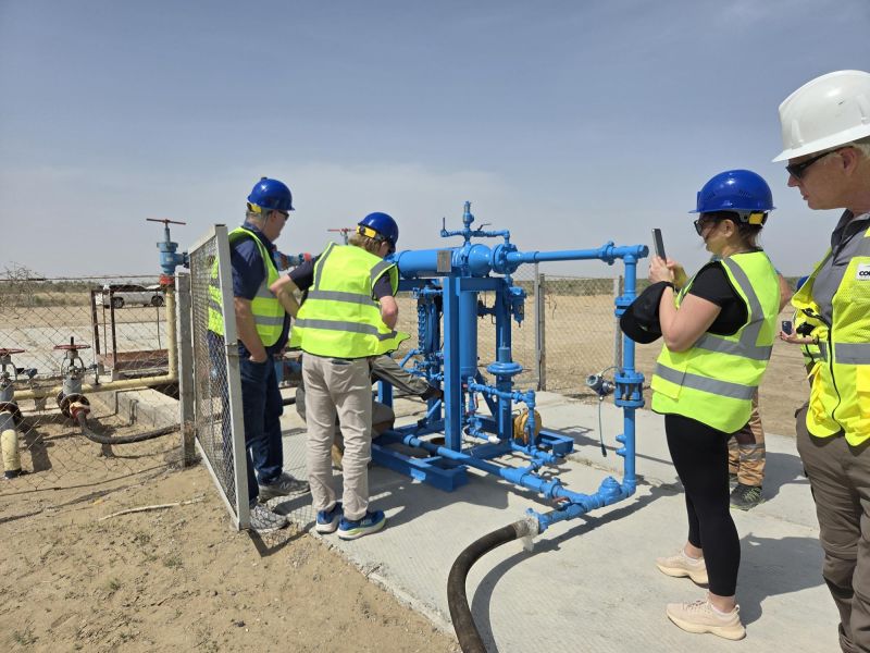
Innopipe has already achieved 100+ installations globally with flexible configurations.
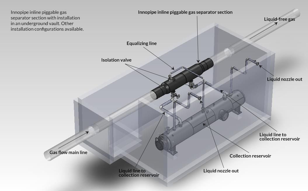
Innopipe Is Comprised of 3 Distinct Sections
The Innopipe inline gas separator and piggable drip system has three sections:
1. Separator section
2. Interconnecting piping
3. Collection reservoir
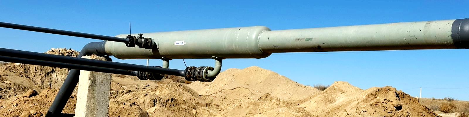
Separator section
Has a slotted inner section (to match line pipe) and a larger outer chamber that covers the slotted line pipe section.
Separator sizes: 1” to 60” pipeline designed to match pipeline size and grade. Beveled for inline welding or flanged.
Outer chamber: Covers the slotted inner pipe and directs liquids to flow into the collection reservoir. Material selected to meetservice requirements.
Overall length: Depends on separator size and flow rate/velocity ranges.
Piggable: Can be used for piggable or non-piggable installations.
Design pressure: Designed to specified pipeline pressure
Gas velocity max: Gas Typically limited only by pipeline capacity
Design temperature: As required
Sour service: Yes, if required
Corrosion allowance: If required
Nozzles: All nozzles and reinforcements are set through, full penetration welded, and magnetic particle examined. Sized forexpected flow rate.
Design compliance: Designed to ASME section VIII2013 Edition and manufactured to ANSIB31.8,2012 Gas Transmission andDistribution Piping Systems (DOT192 compliant). Design factor 0.5 (50% SMYS)
Liquids removal efficiency: Typically 99.5% free of liquids
Installation options: Buried, above ground or in vaults
Pressure drop: Less than 1 psi across separator
Interconnecting piping section
Designed to allow liquid to flow from separator into collection reservoir.
Lines are sized for separator conditions. Isolation valves are used to shut off flow from separator to collection reservoir or close when pigging.
Extended valve stem to surface to allow for shutoff and reservoir isolation.
Pipedesign: ANSIB31.3 or ANSIB31.8 piping design factor 0.5
Collection reservoir section
Size: Size based on factors such as amount of liquid expected, ability to remove liquid on timely basis or a mount of time beforeliquids can be removed. Consider liquids handling (i.e. blowdown, tank, and pumped back into the line) – size depends onthe operation.
Press/temprating: Designed to system requirement
Installation: Typically buried or in vaults – eliminates freezing in cold environments.
Corrosion allowance: As requested
Internal coating: As requested.
Nozzles: 2 liquid inlets from separator section
2 liquid drains off bottom
1 blowdown to surface with stinger to bottom of collection reservoir
2 level indicator or H alarm
Manway if coating required.
Sour service: Available
Design compliance: Designed ASME sectionVIII2013Ed and manufactured to ASMEB31.8.;
NDE: As required by specifications.
Options:
●Levelcontrol/alarms
●Valves (typically supplied by user to match installed base)